Managing ‘clean water’
Contour drains
Erosion Control
Managing ‘dirty water’
What, why, when and issues to look out for
What
Water that is ‘dirty’ has run through a works area and contains sediment, so needs treatment before it is discharged. Dirty water is managed by creating a diversion, which a non-erodible channel and/or bund that conveys dirty water. Diversions are constructed for a specific ‘design storm’, which means the storm of annual return probability – for example, 5% annual exceedance probability (AEP) storm + 300mm.
The channels are usually constructed across a slope. This design means that a bund is needed on the downslope side to prevent flow from spilling out of the channel.
Runoff diversions may be:
- Drains, which can be lined with an erosion-resistant material such as spray-on copolymer channel liner or needle-punched fabric
- A combination bank or bund with excavated upslope channel
- An earthen bank, often made from compacted soil.
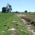
Dirty water diversion bund directing site water to a sediment retention pond (Source: SouthernSkies).
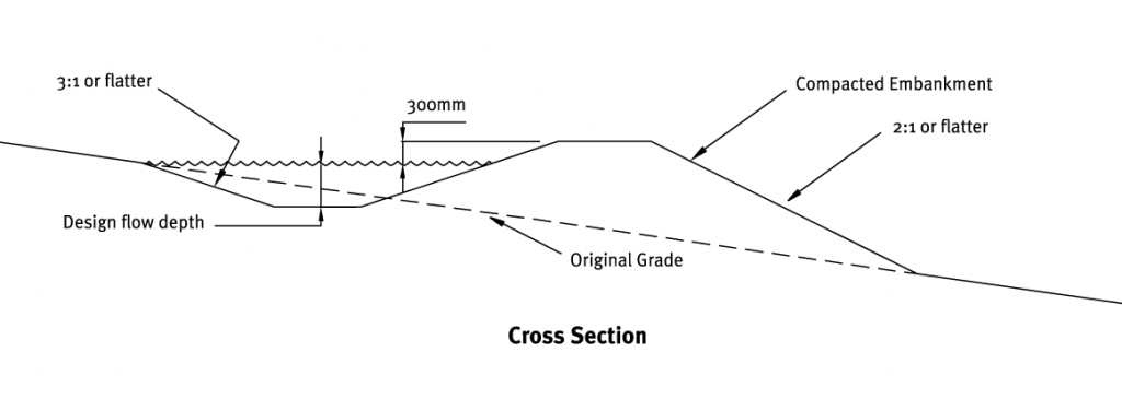
Cross section of a diversion bund.
Why
Dirty water diversions convey sediment-laden water within the disturbed area to a sediment retention device so the water can be treated.
When
Dirty water diversions and bunds divert sediment-laden water to an appropriate sediment retention device like a sediment retention pond or decanting earth bund. These are typically located within or at the lowest extent of the disturbed area.
Issues to look out for
Dirty water diversions have the following limitations:
- All dirty water diversion channels need to be stabilised. It is best to use copolymer spray-on channel liners.
- If the longitudinal gradients are more than 2%, you need to do additional preventative activities to stop scour at the corners and sediment depositing where the slopes flatten off. Check and maintain these areas frequently.
- You need to size and construct diversions for the site conditions. Don’t confuse them with contour drains.
- In some examples (eg steep slopes and/or unstable ground), specific geotechnical design will be required to make sure that the diversion works.
- Subsoils that are erodible and/or prone to piping failures may be exposed along the invert of excavated diversions. If left unchecked, serious lower slope stability problems may result, so make sure that the subsoils are stabilised properly before you put the diversions into use.
- On steep slopes it is often difficult to construct a channel bank or drain with the required channel capacity. You also need to consider where the sediment retention device is located.
- Access for maintenance can be difficult once construction has started.
Design essentials
Whichever type of runoff diversion you are using, the following points are design essentials for the tool to work.
When choosing the location
- Determine the location of any diversion measures by considering the contributing catchment area, outlet conditions, topography, land use, soil type, length of slope, seep planes (if seepage is an issue) and the development layout
- Where practical, choose a route for structures that avoids trees, existing or proposed service infrastructure, existing or proposed fence lines, and other natural or built features.
When designing downslope dirty water diversions
- Diversions where catchments are bigger than 5 hectares (ha) need a formal design.
- A standard dirty water diversion arrangement may be used on sites smaller than 5 hectares. Look at the design diagram for design features of a diversion bund:
Cross section of a diversion bund.
- Diversions must have sufficient capacity to safely carry the flow from a 5% annual exceedance probability (AEP) storm, plus a freeboard of 300 millimetres (mm).
- Include all calculations, design notes, drawings, etc. in the site’s ESC Plan.
- Diversion gradients greater than 2% may need to be lined, to minimise erosion.
- If design velocities are over 1 metre per second (m/sec), you may need a channel liner to prevent erosion.
- The grade along the diversion should be as even and uniform as possible. This is because increases in grade can cause scour, and sudden decreases can cause sediment to accumulate, so that the drain overtops.
- Outlets from all diversions must discharge to an appropriate sediment control device for treatment.
When designing drop out pits
- Construct a ‘drop out pit’ within the dirty water diversion to allow heavier sediment particles to settle before they enter the sediment retention device, to reduce the load on the device. Drop out pits are approximately 500–1,000 mm deep and 1,000 mm wide. They are easier to maintain and usually cheaper to desilt than the sediment retention device itself.
- Consider lining the entrance and exit of the drop out pit to prevent scour. They should be smooth and level. The entrance should be battered.
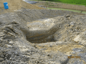
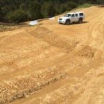
Drop out pit. Note that the inlet and outlet should be level and smooth (Source: SouthernSkies Limited).
Construction and operation
When constructing and operating diversion channels and bunds
- Plan and construct all dirty water diversion works as part of the initial site establishment and development
- Define the route and survey it to achieve the correct gradient
- Construct drains with a uniform grade along the invert, as sudden decreases may cause sediment to accumulate, causing the bank to overtop
- Make sure that the bunds associated with the diversions are well compacted and stabilised. In some cases, this may require specific geotechnical design to ensure the stability and integrity of the structure
- All dirty water diversion channels need to be stabilised along the whole flow path. It is best to use copolymer spray-on channel liners
- Monitor diversions for erosion. Depending on the type of soils on site, erosion control will probably be needed where the gradients are greater than 2% or where the design velocities exceed 1 m/sec
- Ensure the finished cross-section meets all design requirements
- Provide an adequate outlet for each diversion, eg to a sediment control device.
Maintenance and decommissioning
When maintaining dirty water diversions
- Inspect weekly, after every rainfall and during periods of prolonged rainfall, for scour and areas where diversions may breach. Repair immediately if necessary to ensure that the design capacity is maintained.
- Remove any accumulated sediment deposited in the diversion channel where there is a risk of overtopping due to a lack of freeboard.
- Check invert and outlets to make sure that these remain free from scour and erosion. These points may require geotextile lining to avoid scour.
- Look for low spots, areas of water ponding, formation of tunnel gullies, sediment deposition and debris blockage.
- Check for stabilisation cover and do remedial work as needed.
- Take particular care to protect perimeter diversions against damage from earthmoving operations. Reinstate the diversions if damaged.
When decommissioning dirty water diversions
- Remove diversions only when all disturbed areas above the dirty water diversion have been stabilised.
- Fill, compact and shape all disturbed areas to blend in with the finished landform.
- Stabilise all the areas that were disturbed as part of the removal process. Apply seed and fertiliser, and protect with mulch or erosion-control blankets if required.