Sediment retention ponds
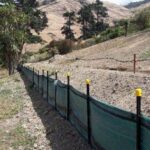
Silt fences
Sediment Control
Decanting earth bunds
What, why, when, and issues to look out for
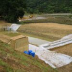
What
Decanting earth bunds (DEBs) are an impoundment area formed from a temporary bund or ridge of compacted earth. (‘Impoundment area’ means that they are designed to enclose and hold back dirty water.)
Why
DEBs provide an area where ponding of runoff can occur and suspended material can settle out before runoff is discharged.
When
DEBs are mainly used in the following situations:
- To treat sediment-laden runoff
- If concentrated flows of sediment-laden runoff are happening
- The soil type needs flocculent treatment to improve efficiency
- The catchment area is too small for an SRP (generally less than 0.3 ha)
- The slopes of the contributing catchment and/or concentrated flows dictate that silt fences or super silt fences are not appropriate.
DEBs are particularly useful for controlling runoff after topsoiling and grassing before the vegetation has become established. Use them along with other tools from this toolbox as part of a treatment train, mix and match approach.
Issues to look out for
DEBs have the following limitations:
- You might need specific geotechnical design to impound the required volumes of water (depending on geotechnical constraints).
- They are less effective on steeper slopes, where the runoff velocities are greater.
- Their recommended maximum catchment is 0.3 ha.
- DEBs can be a safety hazard if they are not fenced appropriately and if safety rules are not followed. Check the safety requirements of Worksafe NZ.
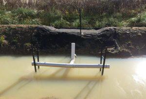
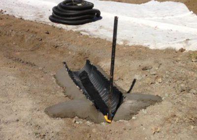
DEB decanting t-bar system (Source: SouthernSkies).
Design essentials
DEBs are often installed in challenging locations where achieving all of the following design criteria may be impractical. As these criteria are interrelated, if you have to compromise any one of them, make sure that your overall approach is still achieving these goals:
- Maximise the volume of storage, to maximise the duration of settlement
- Reduce velocities through length-to-width ratios and/or baffles, to promote settlement
- Maintain an appropriate dead water depth and volume to dissipate inflow energy, stop settled sediment from being re-suspended and to store settled sediment
- Maintain an appropriate live water depth and volume, to promote settlement
- Make sure that the installed device is structurally sound and includes a stabilised spillway sized to accommodate the 1% AEP event without eroding
- The base of the bund should slope gently towards the invert batter.
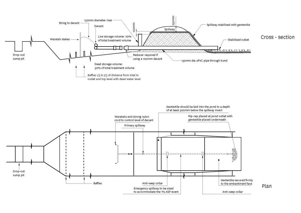
Decanting earth bund plan and cross section design.
Size
Size the DEB based on the contributing catchment area. The following calculations define the total storage volume, which is measured from the base of the DEB to the top of the primary spillway, and are the minimum standards:
- On earthwork sites with slopes less than 18% and less than 200 m in length, construct a DEB with a minimum volume of 1% of the contributing catchment area (10 m³ for each 1,000 m² of contributing catchment).
- On earthwork sites with slopes greater than 18% or greater than 200 m in length, construct a DEB with a minimum volume of 2% of the contributing catchment area (20 m³ for each 1,000 m² of contributing catchment).
- The slope angle is determined by the slope immediately above the DEB, or by the average slope over the contributing catchment, whichever is greater. The slope angle should also be the greater of the pre- or post-construction slope.
- Oversizing the DEB improves the sediment retention and treatment potential and helps to cope with intense storms. Experience in other regions shows that building DEBs 30% larger than the minimum design above is beneficial.
- Treat dirty water flowing into DEBs with coagulants and flocculants to achieve good water quality in the discharge. If you plan to batch dose only, rather than ‘online’ then the DEB must be sized to detain and treat all runoff from the design storm. Detaining and treating only part of the design storm is ineffective and unacceptable as most of the dirty water will have been discharged before detention and treatment can be achieved.
Shape
- Maximise the distance between the inlet and the outlet (including the emergency spillway) to reduce the risk of short circuiting and to promote quiescent (inactive) conditions
- The base of a DEB should be at least 2 m wide
- The length-to-width ratio of the DEB should be no less than 3∶1 and no greater than 5∶1. This ratio is measured at the height of the primary spillway
- The length of the DEB is measured as the distance between the inlet and the outlet (decant system). As a minimum the inlet should be 5 m from the outlet
- Make sure that the DEB has a level invert to promote the even and gradual dissipation of the heavier inflow water across the full area of the DEB.
Depth of pond
- Limit the depth of DEBs to a maximum of 1 m embankment height. (Note: By excavating to form the dead storage volume below existing ground level, you can increase the overall depth.)
Dead storage (permanent storage)
- Dead storage is the component of impoundment volume that does not decant and remains in the DEB. It is important for dissipating the energy of sediment-laden inflows.
- Make sure that dead storage is 30% of the total DEB storage by positioning the decant 0.30–0.40 m above the invert of the DEB.
Live storage (decant storage)
- Live storage is the volume between the decant outlet level and the crest of the DEB primary spillway
- Make sure that the live storage volume capacity is 70% of the total DEB storage.
Decanting/outlet dewatering device
- Dewater the DEB to remove the water within the upper water column (live storage) without removing any of the settled sediment, and without removing any appreciable quantities of floating debris.
- Use a floating T-bar dewatering device (the same as used in a sediment retention pond or SRP), which allows for the decanting of the cleaner surface water from the top of the water column. (Note: The T-bar is the minimum standard, and you can use a 100–150 mm diameter device. There are also skimmers available (which float on the surface).
- The recommended decant rate from a DEB is the same as for SRPs, 0.3 litres/second/1,000m² (or 3 litres/second/ha) of contributing catchment. This rate ensures that appropriate detention times are achieved.
- To calculate the number of holes (10 mm diameter) required to achieve the decant rate described above, allow 133 holes per 1 ha of contributing catchment (ie divide the number of ha of contributing catchment by 0.0075). Divide the total number of holes evenly among the number of decants.
- The T-bar decant must be able to operate through the full live storage depth of the DEB.
- Make sure that the T-bar decant float is securely fastened with steel strapping directly on top of the decant arm. Weight it to keep the decant arm submerged just below the surface through all stages of the decant cycle. This will also minimise the potential for the decant holes getting blocked by floating debris. The most successful method found to date is to weight the decant arm by strapping a 0.9 m long waratah between the float and the decant (approximately 2.0 kg of weight).
- Lay the 150 mm diameter discharge pipe at a 1–2% gradient, and compact the fill material around it using a machine compactor.
- At the inlet end of the outlet pipe install a 90° Tee to accommodate the primary spillway. Install a 150–100 mm reducer and short 100 mm section to provide a connection for the T-bar.
- The decant should include a mechanism to allow outflows from the DEB to be temporarily stopped. This is to facilitate batch-dosed flocculant treatment and as a contingency if there is a spill or a discharge of contaminants. It will allow contaminated runoff to be retained and prevent it from discharging from the site. We recommend a rope and pulley system to lift the decant, but other options such as plumbing bungs, valves or screw-on end caps can also be used, depending on the details of each DEB.
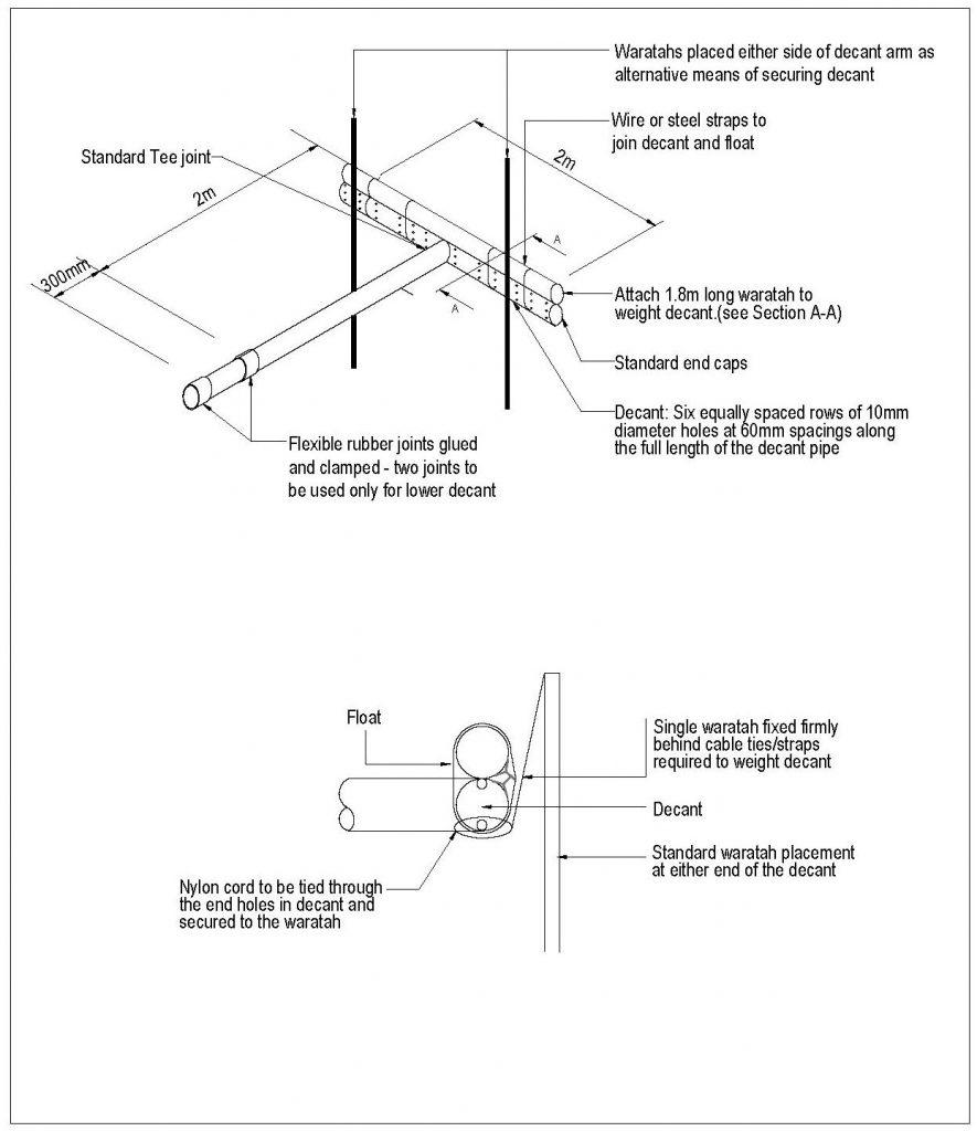
Standard decant t-bar design.
Primary spillway
- All DEBs need a piped primary spillway.
- Use a 150 mm upstand as a primary spillway.
- The primary spillway should be at least 350 mm lower than the top of the DEB embankment and at least 100 mm lower than the emergency spillway crest. Make sure that the riser and the discharge pipe connections are all completely watertight.
Emergency spillway
- All DEBs need an emergency spillway
- Emergency spillways must be able to accommodate the 1% AEP event without eroding
- Design the emergency spillway as a stabilised trapezoidal cross-section with a minimum bottom width of 1.5 m, unless specific design calculations have confirmed a smaller emergency spillway will accommodate the 1% AEP event
- Design the emergency spillway with a minimum of 100 mm freeboard height above the primary spillway
- Ensure that the emergency spillway has a minimum freeboard of 250 mm (between the invert of the spillway to the lowest point on the top of the bund).
Baffles
- As with SRPs, baffles can be used to increase the performance of the DEB. Install them across the width of the bund and at the dead water level. Make them with porous open mesh cloth and stake them securely into the full width of the bund.
Drop out pits
- Drop out pits are cheap to install and easier to clean than DEBs and are a useful part of the toolbox/treatment train approach
- Install them into dirty water channels upstream of DEBs
- Make them at least 1m across and put them somewhere accessible for sediment removal
- Make sure that the inlets and outlets are smoothly formed and compacted. It is a good idea to protect the inlet and outlet with spray-on copolymer channel liner
- Clean them out regularly and put removed sediment in an appropriate and protected location.
Drop out sump pit.
Flocculent treatment
DEBs need flocculent treatment to increase their efficiency. For more information, see the coagulants and flocculants section and Auckland Council’s Technical Publication TP227 – The Use of Flocculants and Coagulants to Aid the Settlement of Suspended Sediment in Earthworks Runoff: Trials, Methodology and Design, June 2004 (PDF 783 kB).
There are various coagulants and flocculants available. Investigate and use the best-performing treatments or combinations for your situation.
Dirty water will receive flocculent treatment when it flows across a floc sock in the channel upstream of DEB. Note the concrete wingwalls which ensure that the floc sock is not outflanked.
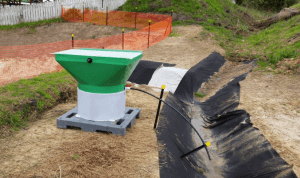
A portable rain-activated flocculent dosing system will improve settlement of sediment in DEBs (Source: Erosion Control Limited).
Construction and operation
- Form clean water diversion bunds or drains to isolate the DEB construction area.
- Install a silt fence or other appropriate sediment control below the construction area.
- Clear areas under proposed fills of any topsoil or other unsuitable material.
- You might need to key in large fill embankments. Make sure that you build the embankments, including the foundations, to appropriate engineering design standards.
- Use only approved fill.
- Place and compact fill in layers to the engineer’s specifications.
- Don’t place pervious materials (permeable, that water can pass through) such as sand or gravel within the fill material.
- Construct fill embankments approximately 10% higher than the design height to allow for the material to settle. Install appropriate pipe work while you are installing the embankment, and compact around this appropriately. Where possible, install the discharge pipe through the embankment once the embankment fill height provides enough cover over the pipe to continue filling. Make sure that the backfill around the outlet pipe is impermeable.
- Install the emergency spillway. The outer emergency spillway crest and batter need to be very well stabilised. Compact the fill material of the spillway batter well. Where possible, build emergency spillways in well vegetated, undisturbed ground (not fill) and discharge over long grass. If the emergency spillway is on bare soil, provide complete erosion protection with tools such as grouted rip-rap, asphalt, erosion matting/geotextile or concrete. When using geotextile for emergency spillway stabilisation, the batter face must be smooth and all voids eliminated. If you are using geotextile, lay a soft needle punch geotextile first and then cover it with a strong woven low permeability geotextile. Space pins holding the geotextile down no further than 0.5 m apart, over the full area of the emergency spillway.
- Securely attach the decant system to the horizontal pipework. Position the T-bar decant at the right height by tying 5 mm nylon cord through decant holes at either end of the decant arm and fastening it to waratahs driven in on either side of the decant. Use a flexible thick rubber coupling to connect the decant arm and the discharge pipe. To provide sufficient flexibility, install two couplings. Fasten the flexible coupling using strap clamps and glue. Make all connections watertight.
- Don’t put pervious material such as sand or scoria around the discharge pipe.
- Install baffles across the width of the bund at the dead water level.
- Fully stabilise the external batter face straight away, by vegetative or other means, following the site’s ESC Plan. Make sure that all bare areas associated with the DEB are stabilised with vegetation if the DEB is to remain in place over winter.
- Provide an all-weather access track for maintenance.
- Install and commission any flocculent treatment devices.
- Produce an as-built to confirm that all design criteria have been met. Fix any problems as needed.
- Install sediment-laden diversions to direct all runoff for the catchment area to the DEB.
Maintenance and decommissioning
When maintaining DEBs
- Inspect DEBs daily, and before and after each rainfall.
- Clean out drop out pits regularly to help the functioning of the downstream DEB.
- Clean out DEBs before accumulated sediment reaches 20% of the total DEB volume. To help gauge sediment loads, consider installing a marker post.
- Clean out DEBs with high capacity sludge pumps, or with excavators (long reach excavators if needed), loading onto sealed tip trucks or to a secure area.
- The ESC Plan should identify disposal locations for the sediment removed from the DEB. There must be no resulting direct discharge to receiving environments. Stabilise all disposal sites as required and approved in the site’s ESC Plan.
- Immediately repair any damage to DEBs caused by erosion or construction equipment.
When decommissioning DEBs
- Stabilise the contributing catchment or install other appropriate sediment retention devices.
- Dewater the DEB. Do not discharge dirty water, like the remaining dead water, from the DEB into waterways as this is an offence. Find alternatives like treating through a sediment tank, discharging to land, or tankering it away for secure disposal.
- Remove and correctly dispose of all accumulated sediment.
- Remove fabric, concrete, pipe and other construction materials.
- Backfill the DEB and compact the soil, re-grade it as needed.
- Stabilise all exposed surfaces.
Monitor performance
- Monitor the performance of DEBs by regularly checking the quality of water flowing in and out (see monitoring section on our principles page for further information)
- Use this information to help improve erosion control measures and the DEB’s performance
- If concentrations of suspended solids in inflows to the bund are very high, check whether your erosion control measures are effective and adapt or improve them
- Likewise, if drop out pits and the bund itself seem to be accumulating sediment rapidly or frequently need cleaning out, then assess the performance of your erosion control measures
- Reducing the sediment flowing into the bund by effective land management is the best way to achieve good water quality downstream, rather than over-relying on water treatment.